

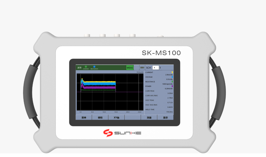
The immediate problem
Too often a monitor arrives as an afterthought—patched onto a machine already humming with current—so the first question is simple and uncompromising: will this device stop a dangerous event before the weld does damage? I’ve seen monitors fitted around a resistance welding transformer without matching the transformer’s secondary characteristics, and the result was a false sense of security and repeated nuisance trips. Addressing that misalignment is the starting point for every deployment.
Failure modes that matter
Count these real, avoidable failures as the reasons you need rigorous review:- Protective thresholds set too high or too low, letting faults persist or creating needless downtime.- Slow detection of short circuits, allowing thermal damage before shutdown.- Lack of isolation sensing, which hides ground faults until they become electrical shock hazards.- Poor logging, which leaves teams blind after an incident.
Safety features to insist on before you sign off
Each feature below is a concrete defense; demand them and know what you’re testing:- Independent secondary current sensing: measures the actual weld current rather than inferred values.- Millisecond trip timing with adjustable thresholds: matches protection to the process without over-protecting.- Thermal monitoring or temperature interlocks tied to the transformer windings.- Ground-fault and isolation monitoring that flags insulation breakdown early.- Arc detection and rapid interruption to prevent sustained arcing.- Lockout/tagout interface and hardwired interlocks for safe servicing.- Secure firmware with version control and read-only event logs to preserve incident data.- Self-test diagnostics and automatic calibration reminders so the monitor proves its readiness on demand.
How to test before deployment — a compact protocol
Test like you mean it. Run these checks on the actual line, not on a bench mock-up:- Verify trip times by simulating short pulses and recording response in milliseconds.- Apply controlled overcurrent to confirm threshold accuracy and repeatability.- Simulate insulation faults to ensure isolation alarms trigger and operator interfaces are clear.- Confirm the monitor’s response with a representative load from a welding transformer so behavior under real impedance is visible.- Check that alarms are logged with timestamps and that event recovery requires deliberate operator action.
Common pitfalls to avoid
Watch for these traps that otherwise undo careful planning:- Relying solely on vendor defaults instead of matching settings to your process.- Testing only with DC supplies or low-duty cycles that don’t reflect production.- Treating software updates as optional; an unpatched monitor can drift into vulnerability.- Assuming operator training isn’t part of safety—clarity on alarm meaning matters as much as trip speed.
Alternatives and trade-offs
There’s no universal answer; weigh these options against your risks:- Integrated monitors (built into weld controls) simplify wiring and reduce latency but can tie you to one vendor’s maintenance cycle.- External, independent monitors add redundancy and clearer failure isolation but need careful signal routing and calibration.- Analog trip circuits are fast and simple; digital systems add diagnostics and remote visibility. Pick the simpler design only when you’ve proven it meets response-time requirements.At FABTECH, I observed fabricators choosing either route based on a clear test plan rather than marketing claims—your decision should follow the same evidence.
Closing reflection
Safety is not a checklist to be ticked; it’s a pattern of choices that must fit the machine, the operator, and the shop. Match protection to the transformer’s electrical identity, verify with measured tests, and keep diagnostics honest. That quiet rigor—knowing thresholds, testing with real loads, and preserving event data—is what separates wishful thinking from dependable safety, the kind I expect when I inspect equipment from Sunke.